Measurements of NXT motors
We have been curious how do actually the signals that control the NXT motors look like. The NXT output cable has 6 wires:
MA0, MA1 - "PWM" output signals to actuators GND, POWERMA - optional power source for embedded devices TACHOA0, TACHOA1 - internal rotation sensors
The MA0, MA1 are compatible with the RCX's motor, so they are not any kind of control signal to a servo motor, they are simply connected to two poles of a DC motor so that they can drive it forward or backward depending on changing polarity.
When the motor is running full-speed, the MAX signals are simply connected to ground and battery voltage to drive the motor maximum speed. When the motor strength is decreased, the power is supplied in impulses with length proportional to the desired power:
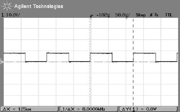
Plot of the MA signal when NXT motor is running half speed (50%).
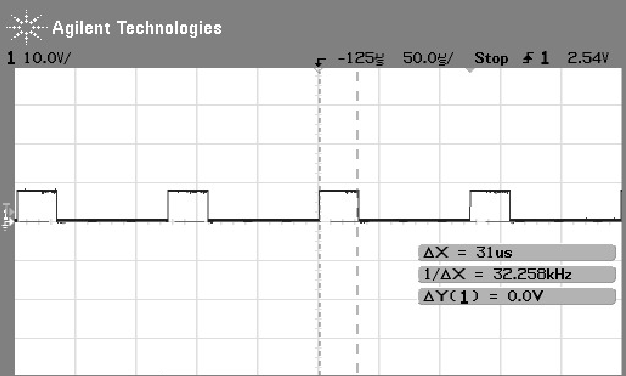
Plot of the MA signal when NXT motor is running 75% speed.
(note that the drive is supplied when the signal is low;
the other MA signal is always high). Similarly, the signal looks
the same, just inverted for 25% power.
So the frequency of oscillations generated by NXT is 8kHz.
And it is possible to drive the old RCX motors using these outputs and the conversion cable supplied by LEGO.
It can be interesting to compare these measurements to signals generated by RCX: we look at both the standard firmware and BrickOS firmware. Those signals look like this:
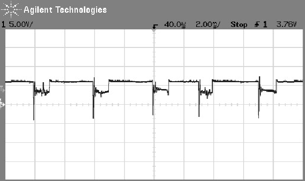
RCX motor running on power 4 out of 7 with standard firmware (and NQC program).
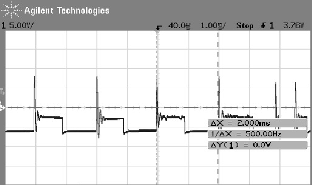
RCX motor running on half of full power with BrickOS firmware.
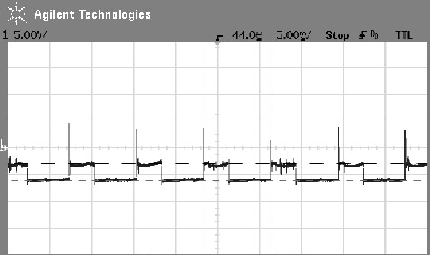
RCX motor running on 3/4th of full power with BrickOS firmware.
The NXT output signals seem to be able to eliminate overshoot, and other ugly effects seen
in the RCX motor plots. The RCX oscillates its motor output on 500 kHz in both firmwares.
Finally, once we had an oscilloscope on, we also looked at the signal on the RCX's activated light sensor, it looks as follows (with BrickOS firmware):
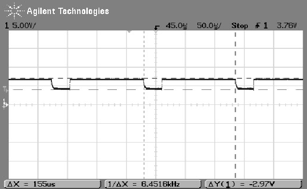
RCX active light sensor sampling.
It appears that the sampling frequency is about 6.5 kHz.