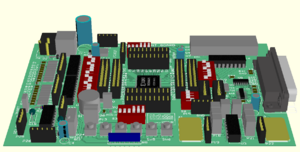
XilinxEVB/en
Author: Juraj Michálek
Xilinx Evaluation Board
Description
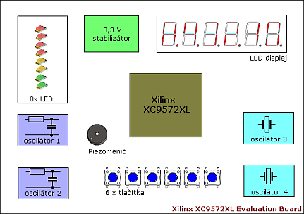
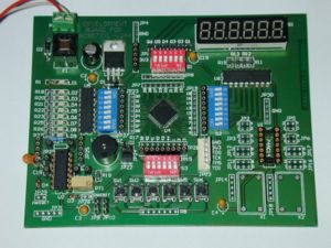
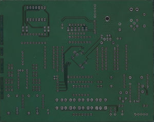
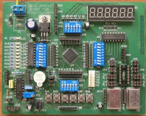
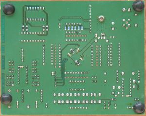
The purpose of this evaluation board (EVB) is to acquire experiences with the CPLD Xilinx family XC95xxXL. This board uses XC9572XL, which contains 72 cells. Their inerconnections gives the required function.
Peripheral:
6 multiplexed 7-seg LED display with power drivers enables to make a counter and other number displaying devices.
8 LEDs for differet signaling purposes, indicators of the internal states of the CPLD etc. LEDs are driven with ULN2803A transistor array with OC outputs. They can be used also for driving an external applications.
2 x non-symetrical RC oscillator using 74AC14 (U2). One of the oscillator enables frequency changing using the multiturn trimer. Both oscilator frequencies are controlled by an R and C components, according the f=1/(3RC) rule. Inhibit input can stip the oscillator (High level). Oscillator output is a cca 1:1 . Can be used as a clock source especially for "slow" applications.
2x hybrid XT oscillator, clock source for higher frequencies, especially for more precise and stable applications. Oscillator output is usually harmonic and it can be shaped to the rectangle using U1 Schmitt triggers.
6x pushbuttons. Spoločný vývod spínačov, ako aj spoločný vývod R-siete vyvedený na pinovú lištu, umožňuje nadstavenie aktívnej úrovne pri stlačení tlačítka. (teda či pri stlačení polezie do CPLD L alebo H. Tlačítka nie sú úmyselne ošetrené voči zákmitom. Toto ošetrenie je možné previesť priamo v CPLD (aspoň si to myslím ;-) )
Buzzer enables to create sound effects with the CPLD. Piezo buzzer without an internal oscillator is used. It is necessary to use a frequency signal to drive it. Pin liste enables to connect also the higher voltage than boards 3,3 V. Correction: it is necessary to connect a discharge resistor (cca 1k) paralell to the piezoelement. New version of the board already contains this resistor.
All the peripherals are disconnectable using DIP switches. This enables to use all the I/O Pins also for another special purposes. Pin contacts on each CPLD pin are used for interconnections or for logic probe or analyser connection.
EVB is powered from the external unstabilised power supply min. 5 Voltds. Required internal power supply 3,3 V is delivered from the LF33CV stabilisator. Power consumption depends on the CPLD operational frequency and on the peripheral activities. Filter F1 is for filtering disturbances, especially when powering from cheap wall adapters. It can be omitted. During the board population it is recommended pre-heating of the board e.g. hot air gun, otherwise the ground plane will drain most of soldering gun heat.
Board dimensions: 135 x 107 mm.
Contact: ICQ: 209 598 598 ; mail: evb.cpld@gmail.com
Images
Programmer
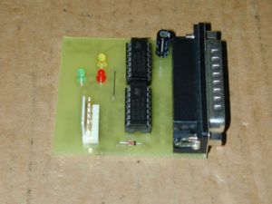
The board is to be programmed using the simple paralell port programmer.
Its schematic diagram is directly on the Xilinx webpage, or e.g. here also with the PCB.
Xilinx EVB - new version
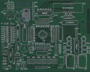
New version of the board uses the bigger CPLD (XC95144XL-TQ100). Also the JTAG LPT programmer is onboard and additional 8 LEDs is available. There is also a reduction for the XC9572XL PC44 chip. Another reductions are planned. Also the XC9572XL TQ100 chip can be used without problems.
Note: Instead 74HC family also the 74AC family can be used and vice versa.
3D model of the new version of the board:
Downloads
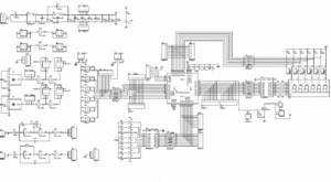
- Schematic diagram EVBXC9572XL in pdf format Media:schema.pdf
- Schematic diagram EVBXC95144XL in pdf format Media:schema95144XL.pdf
- Schéma a osadzovací plán redukcie PC44_TQ100 pre EVBXC95144XL vo formáte pdf Media:PC44_TQ100.pdf
- Population of the EVBXC9572XL Media:doska.pdf
- Population of the EVBXC95144XL Media:doska144.pdf
- Bill of Material Media:DB_XC9500XL_VQ44_rev0.xls
- Bill of Material for EVBXC95144XL Media:DB_XC95144XL_rev0.xls
Examples
- Abel: The simplest logic
- Abel: Stepper motor controller
- Abel: Stepper motor controller with microstepping
Links
- Short video
- Xilinx: The Programmable Logic Company
- XC9500XL Resources
- Digilent - boards producent, also the examples
- Open Cores (processors, communications,...)
--- --- --- --- --- RoboWiki: (c) 2006 Robotika.sk --- --- --- --- ---
