Difference between revisions of "First experiments with HB2 PMOD"
(Measurements of HB2 first experiment) |
(explanation) |
||
| (3 intermediate revisions by the same user not shown) | |||
| Line 2: | Line 2: | ||
to DIR1 on [http://www.digilentinc.com/Data/Products/PMOD-HB2/HB2.pdf HB2 PMOD] | to DIR1 on [http://www.digilentinc.com/Data/Products/PMOD-HB2/HB2.pdf HB2 PMOD] | ||
(see also [http://www.digilentinc.com/Data/Products/PMOD-HB2/HB2-brochure.pdf Brochure] | (see also [http://www.digilentinc.com/Data/Products/PMOD-HB2/HB2-brochure.pdf Brochure] | ||
| − | and [http://www.digilentinc.com/Data/Products/PMOD-HB2/PMOD-HB2-rm.pdf Reference manual], | + | and [http://www.digilentinc.com/Data/Products/PMOD-HB2/PMOD-HB2-rm.pdf Reference manual]) , |
and ICP1 (SERVO2 on Cerebot) to EN1 on HB2 PMOD. Then we made a program that generates | and ICP1 (SERVO2 on Cerebot) to EN1 on HB2 PMOD. Then we made a program that generates | ||
an 8 kHz signal with 50% duty cycle on ICP1, while keepng OC1B on, with the hope this | an 8 kHz signal with 50% duty cycle on ICP1, while keepng OC1B on, with the hope this | ||
| Line 25: | Line 25: | ||
All feedback will be appreciated. | All feedback will be appreciated. | ||
| + | |||
| + | ---- | ||
| + | |||
| + | Richard suggests to decrease the frequency of the signal, | ||
| + | perhaps the frequency being too high for this setup so that the motors have time to react (?). | ||
| + | |||
| + | So I tested this with different frequences - 4 kHz, 2 kHz, etc. down to ca. 244 Hz. The observation is that the lower the frequency, the stronger the motor power. And the output signal from | ||
| + | HB2 PMOD when applied to NXT motor looks as follows: | ||
| + | |||
| + | [[Image:hb2_nxt_motor_243Hz.gif]] | ||
| + | |||
| + | The observation shows that the driver manages to keep the signal low only for a relative short | ||
| + | time, after that the signal is overridden by the currents generated by the motor... (?) | ||
| + | See the detail of the same plot: | ||
| + | |||
| + | [[Image:hb2_nxt_motor_243Hz_detail.gif]] | ||
| + | |||
| + | Thus the actual duty cycle unintentionally increases with decreasing the frequency of the signal. | ||
| + | The same signal applied to the old 9V LEGO motor (from RCX's set) looks as follows: | ||
| + | |||
| + | [[Image:hb2_rcx_motor_243Hz.gif]] | ||
| + | |||
| + | I have tried changing the HB2 PMOD part for a different, but they behave exactly the same. | ||
| + | Could that be that the HB2 PMOD is supposed to be used in a different way? | ||
| + | |||
| + | Citing the HB2 PMOD document: "The HB2 has ample capacitance to minimize voltage drop when motor phases are switched on." Does that have anything to do with this? | ||
| + | |||
| + | ---- | ||
| + | |||
| + | So we concluded that everything is actually fine. The difference is that NXT brick can generate a more pretty | ||
| + | signal on the motor because it uses a different driver that connects the pin to the ground when the signal | ||
| + | is on low, whereas HB2 probably just disconnects it. Never mind, the important point is that HB2 provides | ||
| + | power only during the duty cycle as requested by its input. However, due to this motor feedback, lower frequencies | ||
| + | tend to work better. We are therefore using the frequency of about 500 Hz. | ||
Palo (ppetrovic[[Image:zavinac.gif]]acm.org). | Palo (ppetrovic[[Image:zavinac.gif]]acm.org). | ||
Latest revision as of 06:26, 6 December 2006
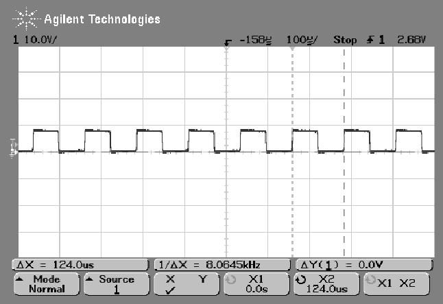
We have connected the OC1B output (SERVO1 on Cerebot) to DIR1 on HB2 PMOD (see also Brochure and Reference manual) , and ICP1 (SERVO2 on Cerebot) to EN1 on HB2 PMOD. Then we made a program that generates an 8 kHz signal with 50% duty cycle on ICP1, while keepng OC1B on, with the hope this is going to steer the motor with 50% power. The NXT LEGO brick steers the motor in this way. The signal we generated looked like this:
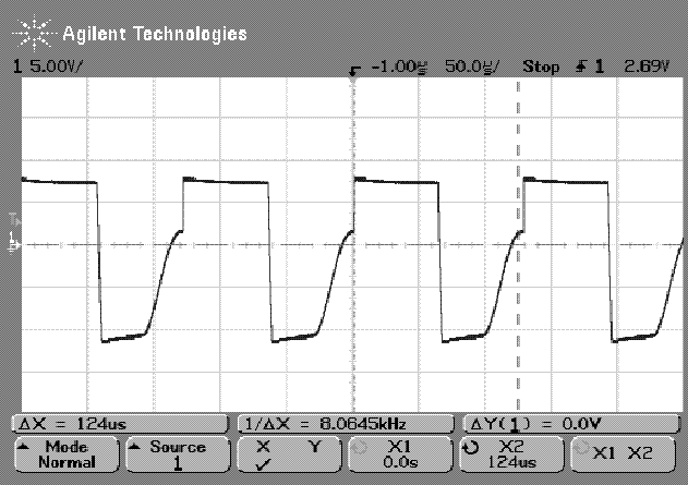
However, the output from the HB2 PMOD when connected to the NXT motor looked like this:
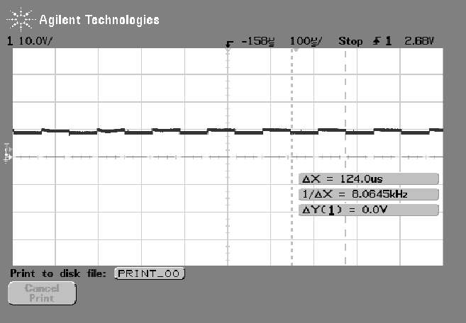
And when connected to the 9V LEGO Motor coming with RCX, it looked like this:
As a result, the NXT motor was beeping at perhaps 8 kHz, but moving very weakly, and the 'RCX motor' was moving on kind of half speed, but with a little bit unusual sound.
The HB2 PMOD is configured to use the VCC voltage for powering motors, which is the 9V from a DC adapter that is able to supply 2A on 9V.
All feedback will be appreciated.
Richard suggests to decrease the frequency of the signal, perhaps the frequency being too high for this setup so that the motors have time to react (?).
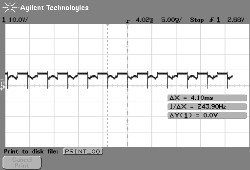
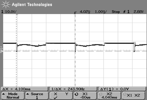
So I tested this with different frequences - 4 kHz, 2 kHz, etc. down to ca. 244 Hz. The observation is that the lower the frequency, the stronger the motor power. And the output signal from HB2 PMOD when applied to NXT motor looks as follows:
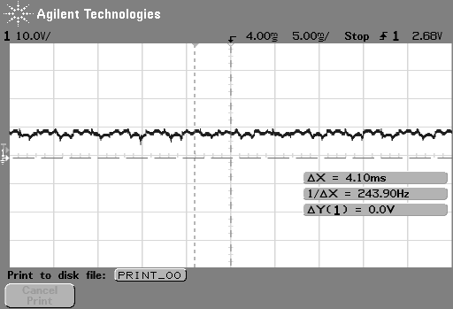
The observation shows that the driver manages to keep the signal low only for a relative short time, after that the signal is overridden by the currents generated by the motor... (?) See the detail of the same plot:
Thus the actual duty cycle unintentionally increases with decreasing the frequency of the signal. The same signal applied to the old 9V LEGO motor (from RCX's set) looks as follows:
I have tried changing the HB2 PMOD part for a different, but they behave exactly the same. Could that be that the HB2 PMOD is supposed to be used in a different way?
Citing the HB2 PMOD document: "The HB2 has ample capacitance to minimize voltage drop when motor phases are switched on." Does that have anything to do with this?
So we concluded that everything is actually fine. The difference is that NXT brick can generate a more pretty signal on the motor because it uses a different driver that connects the pin to the ground when the signal is on low, whereas HB2 probably just disconnects it. Never mind, the important point is that HB2 provides power only during the duty cycle as requested by its input. However, due to this motor feedback, lower frequencies tend to work better. We are therefore using the frequency of about 500 Hz.
