Difference between revisions of "USB pinout"
From RoboWiki
| (One intermediate revision by the same user not shown) | |||
| Line 1: | Line 1: | ||
| + | Connector connection: [[Image:USBconnector.jpg]] | ||
| + | |||
{| | {| | ||
|Pin | |Pin | ||
| Line 29: | Line 31: | ||
PCB connector: | PCB connector: | ||
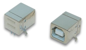
| − | [[Image:USBmale.gif]] | + | Male [[Image:USBmale.gif]] Female [[Image:USBfemale.gif]] |
| + | |||
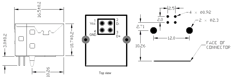
| + | PCB pattern | ||
| + | [[Image:USBpattern.png]] | ||
| + | |||
More info: http://pinouts.ru/Slots/USB_pinout.shtml | More info: http://pinouts.ru/Slots/USB_pinout.shtml | ||
Latest revision as of 09:48, 5 February 2008
| Pin | Name | Cable color | Description |
| 1 | Vcc | Red | +5 VDC |
| 2 | D- | White | Data - |
| 3 | D+ | Green | Data + |
| 4 | GND | Black | Ground |
More info: http://pinouts.ru/Slots/USB_pinout.shtml


