Difference between revisions of "QTI Line sensor"
From RoboWiki
(New page: This page describe how to use Parallax QTI Line Sensor. 200px We will use this [http://www.parallax.com/StoreSearchResults/tabid/768/txtSearch/qti/List/0/SortFie...) |
|||
| Line 63: | Line 63: | ||
Demonstration program for the analogue readings: | Demonstration program for the analogue readings: | ||
<source lang="basic"> | <source lang="basic"> | ||
| + | ' Boe-Bot detects tape with QTI module. | ||
| + | |||
| + | '{$STAMP BS2} | ||
| + | '{$PBASIC 2.5} | ||
| + | |||
| + | ' -----[ I/O Definitions ]------------------------------------------------------ | ||
| + | |||
| + | LineSnsrPwr CON 10 ' line sensor power | ||
| + | LineSnsrIn CON 9 ' line sensor input | ||
| + | |||
| + | ' -----[ Variables ]------------------------------------------------------------ | ||
| + | |||
| + | Sense VAR Bit ' sensor raw reading | ||
| + | |||
| + | ' -----[ Main Code ]------------------------------------------------------------ | ||
| + | |||
| + | DO | ||
| + | |||
| + | Read_Sensor: | ||
| + | HIGH LineSnsrPwr ' activate sensor | ||
| + | PAUSE 1 ' wait until stable | ||
| + | Sense = IN9 ' read sensor value | ||
| + | INPUT LineSnsrPwr ' deactivate sensor | ||
| + | |||
| + | Display: | ||
| + | DEBUG HOME | ||
| + | DEBUG "Sensor ", CR | ||
| + | DEBUG "-----", CR | ||
| + | DEBUG BIN1 Sense, CLREOL | ||
| + | PAUSE 100 | ||
| + | |||
| + | LOOP | ||
</source> | </source> | ||
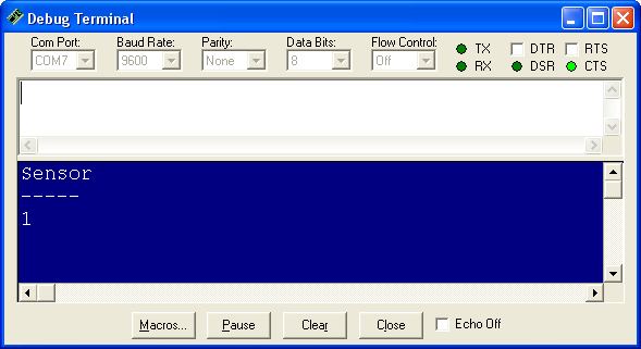
...and its operation | ...and its operation | ||
[[Image:QTIscreenD.png]] | [[Image:QTIscreenD.png]] | ||
Revision as of 22:20, 4 August 2009
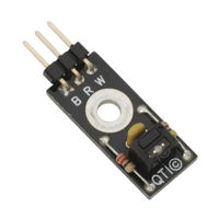
This page describe how to use Parallax QTI Line Sensor.
We will use this QTI Sensor by the Parallax Inc. as a line following sensor. The sensor is available also in set of four sensors together with mounting material for the complete task, see the QTI Line Follower AppKit for the Boe-Bot.
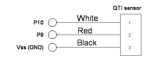
Please, read the following documentation before You start:
Schematic diagram of the connection type 1 (analogue)
Demonstration program for the analogue readings:
' -----[ Title ]----------------------------------------------------------------
' Line Sensor Test

' {$STAMP BS2}
' {$PBASIC 2.5}

' -----[ I/O Definitions ]------------------------------------------------------

LineSnsrPwr   CON 10       ' line sensor power
LineSnsrIn    CON  9       ' line sensor input

' -----[ Variables ]------------------------------------------------------------

Sense         VAR Word     ' sensor raw reading


' -----[ Main Code ]------------------------------------------------------------

Read_Sensor:

  HIGH LineSnsrPwr                   ' activate sensor
  HIGH LineSnsrIn                    ' discharge QTI cap
  PAUSE 1                            ' wait until stable
  RCTIME LineSnsrIn, 1, Sense        ' read sensor value
  LOW LineSnsrPwr                    ' deactivate sensor

Display:

  DEBUG HOME
  DEBUG "Sensor ", CR
  DEBUG "-----", CR
  DEBUG DEC Sense, CLREOL
  PAUSE 100

GOTO Read_Sensor
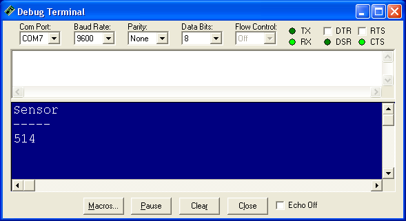
...and its operation
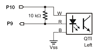
Schematic diagram of the connection type 2 (digital only)
Demonstration program for the analogue readings:
' Boe-Bot detects tape with  QTI module.

'{$STAMP BS2}
'{$PBASIC 2.5}

' -----[ I/O Definitions ]------------------------------------------------------

LineSnsrPwr   CON 10       ' line sensor power
LineSnsrIn    CON  9       ' line sensor input

' -----[ Variables ]------------------------------------------------------------

Sense         VAR Bit     ' sensor raw reading

' -----[ Main Code ]------------------------------------------------------------

DO

Read_Sensor:
  HIGH LineSnsrPwr                   ' activate sensor
  PAUSE 1                            ' wait until stable
  Sense = IN9                        ' read sensor value
  INPUT LineSnsrPwr                  ' deactivate sensor

Display:
  DEBUG HOME
  DEBUG "Sensor ", CR
  DEBUG "-----", CR
  DEBUG BIN1 Sense, CLREOL
  PAUSE 100

LOOP
...and its operation
