Difference between revisions of "SHIFTIN.BS2"
From RoboWiki
(New page: <source lang="basic"> ' SHIFTIN.BS2 ' This program uses the SHIFTIN instruction to interface with the ADC0831 ' 8-bit analog-to-digital converter from National Semiconductor. ' {$STAMP BS...) |
|||
| Line 1: | Line 1: | ||
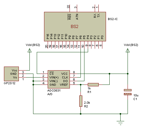
| + | [[Image:SharpSensorSchematic.png]] | ||
| + | |||
<source lang="basic"> | <source lang="basic"> | ||
' SHIFTIN.BS2 | ' SHIFTIN.BS2 | ||
| Line 7: | Line 9: | ||
' {$PBASIC 2.5} | ' {$PBASIC 2.5} | ||
| − | CS PIN | + | CS PIN 9 ' chip select |
| − | AData PIN | + | AData PIN 10 ' data pin |
| − | Clk PIN | + | Clk PIN 11 ' clock pin |
adcRes VAR Byte ' ADC result | adcRes VAR Byte ' ADC result | ||
| Line 33: | Line 35: | ||
LOOP ' repeat | LOOP ' repeat | ||
END | END | ||
| − | |||
</source> | </source> | ||
Latest revision as of 11:33, 6 August 2009
' SHIFTIN.BS2
' This program uses the SHIFTIN instruction to interface with the ADC0831
' 8-bit analog-to-digital converter from National Semiconductor.

' {$STAMP BS2}
' {$PBASIC 2.5}

CS              PIN     9                       ' chip select
AData           PIN     10                       ' data pin
Clk             PIN     11                      ' clock pin

adcRes          VAR     Byte                    ' ADC result


Setup:
  HIGH CS                                       ' deselect ADC

' In the loop below, just three lines of code are required to read the
' ADC0831. The SHIFTIN command does most of the work.  The mode argument in
' the SHIFTIN command specifies MSB or LSB-first and whether to sample data
' before or after the clock. In this case, we chose MSB-first, post-clock.
' The ADC0831 precedes its data output with a dummy bit, which we take care
' of by specifying 9 bits of data instead of 8.

Main:
  DO
    LOW CS                                      ' activate the ADC0831
    SHIFTIN AData, Clk, MSBPOST, [adcRes\9]     ' shift in the data
    HIGH CS                                     ' deactivate ADC0831
    DEBUG ? adcRes                              ' show conversion result
    PAUSE 1000                                  ' wait one second
  LOOP                                          ' repeat
  END
