Difference between revisions of "Line Following Sensor"
From RoboWiki
| Line 9: | Line 9: | ||
* Jon Williams: [http://www.parallax.com/dl/docs/cols/nv/vol3/col/nv85.pdf I2C Fun For Everyone] | * Jon Williams: [http://www.parallax.com/dl/docs/cols/nv/vol3/col/nv85.pdf I2C Fun For Everyone] | ||
| − | * Jon Williams: [http://www.parallax.com/dl/docs/cols/nv/vol5/col/nv115.pdf I2C Again – And the Case for Continuos | + | * Jon Williams: [http://www.parallax.com/dl/docs/cols/nv/vol5/col/nv115.pdf I2C Again – And the Case for Continuos Improvement] |
| − | Improvement] | ||
| Line 26: | Line 25: | ||
' {$STAMP BS2} | ' {$STAMP BS2} | ||
' {$PBASIC 2.5} | ' {$PBASIC 2.5} | ||
| − | |||
| − | |||
| − | |||
| − | |||
| − | |||
| − | |||
| − | |||
| − | |||
| − | |||
| − | |||
| − | |||
| − | |||
| − | |||
' -----[ I/O Definitions ]------------------------------------------------- | ' -----[ I/O Definitions ]------------------------------------------------- | ||
| − | |||
SDA PIN 0 ' I2C serial data line | SDA PIN 0 ' I2C serial data line | ||
SCL PIN 1 ' I2C serial clock line | SCL PIN 1 ' I2C serial clock line | ||
| − | |||
' -----[ Constants ]------------------------------------------------------- | ' -----[ Constants ]------------------------------------------------------- | ||
| − | |||
Ack CON 0 ' acknowledge bit | Ack CON 0 ' acknowledge bit | ||
Nak CON 1 ' no ack bit | Nak CON 1 ' no ack bit | ||
| − | |||
' -----[ Variables ]------------------------------------------------------- | ' -----[ Variables ]------------------------------------------------------- | ||
| − | |||
slvAddr VAR Byte ' slave address | slvAddr VAR Byte ' slave address | ||
devNum VAR Nib ' device number (0 - 7) | devNum VAR Nib ' device number (0 - 7) | ||
| Line 62: | Line 43: | ||
i2cWork VAR Byte ' work byte for TX routine | i2cWork VAR Byte ' work byte for TX routine | ||
i2cAck VAR Bit ' Ack bit from device | i2cAck VAR Bit ' Ack bit from device | ||
| − | |||
| − | |||
| − | |||
| − | |||
| − | |||
| − | |||
' -----[ Initialization ]-------------------------------------------------- | ' -----[ Initialization ]-------------------------------------------------- | ||
| − | |||
| − | |||
devNum = 0 ' device address %000 | devNum = 0 ' device address %000 | ||
| Line 79: | Line 52: | ||
DEBUG CLS, | DEBUG CLS, | ||
"Line Sensor Demo" ' setup output screen | "Line Sensor Demo" ' setup output screen | ||
| − | |||
' -----[ Program Code ]---------------------------------------------------- | ' -----[ Program Code ]---------------------------------------------------- | ||
| Line 85: | Line 57: | ||
DO | DO | ||
GOSUB Read_Byte ' read switches | GOSUB Read_Byte ' read switches | ||
| − | + | ' report | |
| − | |||
DEBUG CRSRXY, 0, 2, "In.... ", BIN5 i2cData | DEBUG CRSRXY, 0, 2, "In.... ", BIN5 i2cData | ||
PAUSE 100 | PAUSE 100 | ||
LOOP | LOOP | ||
| − | |||
| + | END | ||
| − | |||
| + | ' -----[ Subroutines - Don't change nothing here!!! ]---------------------- | ||
' -----[ High Level I2C Subroutines]--------------------------------------- | ' -----[ High Level I2C Subroutines]--------------------------------------- | ||
| − | |||
| − | |||
| − | |||
| − | |||
| − | |||
| − | |||
| − | |||
| − | |||
| − | |||
| − | |||
| − | |||
| − | |||
| − | |||
| − | |||
| − | |||
| − | |||
| − | |||
| − | |||
| − | |||
| − | |||
| − | |||
| − | |||
| − | |||
| − | |||
| − | |||
' Random location read | ' Random location read | ||
| Line 134: | Line 80: | ||
Read_Byte: | Read_Byte: | ||
GOSUB I2C_Start ' send Start | GOSUB I2C_Start ' send Start | ||
| − | |||
| − | |||
| − | |||
| − | |||
| − | |||
| − | |||
| − | |||
| − | |||
| − | |||
| − | |||
| − | |||
| − | |||
i2cWork = slvAddr | %00000001 ' send slave ID (read) | i2cWork = slvAddr | %00000001 ' send slave ID (read) | ||
GOSUB I2C_TX_Byte | GOSUB I2C_TX_Byte | ||
| Line 197: | Line 131: | ||
INPUT SCL | INPUT SCL | ||
INPUT SDA | INPUT SDA | ||
| − | RETURN | + | RETURN</source> |
| − | </source> | ||
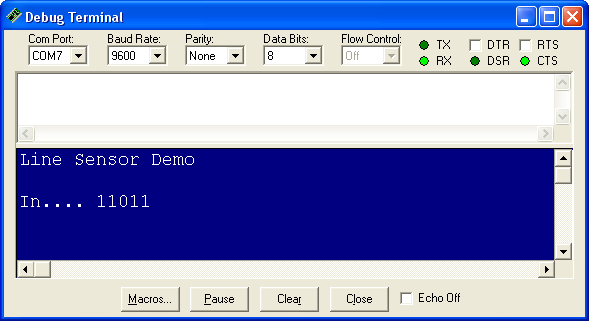
Results: | Results: | ||
[[Image:LineSensorScreenshot.png]] | [[Image:LineSensorScreenshot.png]] | ||
Revision as of 22:07, 4 August 2009
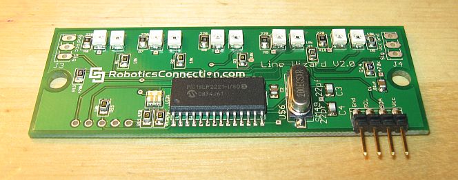
This page describes the connection of the i2c line following sensor to the Boe-Bot robot.
This sensor uses an i2c bus for connection with the processor. To understand more about the communication, read following two articles:
- Jon Williams: I2C Fun For Everyone
- Jon Williams: I2C Again – And the Case for Continuos Improvement
The connection diagram:
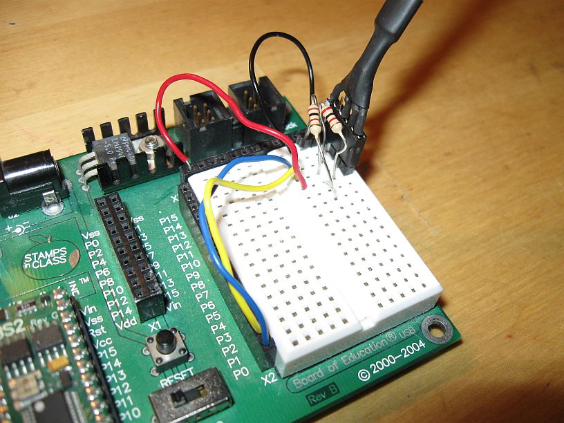
The photo of the connection:
The demonstration software:
'   {$STAMP BS2}
'   {$PBASIC 2.5}

' -----[ I/O Definitions ]-------------------------------------------------
SDA             PIN     0                       ' I2C serial data line
SCL             PIN     1                       ' I2C serial clock line

' -----[ Constants ]-------------------------------------------------------
Ack             CON     0                       ' acknowledge bit
Nak             CON     1                       ' no ack bit

' -----[ Variables ]-------------------------------------------------------
slvAddr         VAR     Byte                    ' slave address
devNum          VAR     Nib                     ' device number (0 - 7)
addrLen         VAR     Nib                     ' 0, 1 or 2
devAddr         VAR     Word                    ' address in device

i2cData         VAR     Byte                    ' data to/from device
i2cWork         VAR     Byte                    ' work byte for TX routine
i2cAck          VAR     Bit                     ' Ack bit from device

' -----[ Initialization ]--------------------------------------------------

  devNum = 0                                    ' device address %000
  slvAddr = $50
  addrLen = 0                                   ' no internal addresses

  DEBUG CLS,
        "Line Sensor Demo"                         ' setup output screen

' -----[ Program Code ]----------------------------------------------------

  DO
      GOSUB Read_Byte                           ' read switches
                                                ' report
      DEBUG CRSRXY, 0, 2, "In.... ", BIN5 i2cData
      PAUSE 100
  LOOP

END


' -----[ Subroutines - Don't change nothing here!!! ]----------------------


' -----[ High Level I2C Subroutines]---------------------------------------

' Random location read
' -- pass device slave address in "slvAddr"
' -- pass address bytes (0, 1 or 2) in "addrLen"
' -- register address passed in "devAddr"
' -- data byte read is returned in "i2cData"

Read_Byte:
  GOSUB I2C_Start                               ' send Start
  i2cWork = slvAddr | %00000001                 ' send slave ID (read)
  GOSUB I2C_TX_Byte
  GOSUB I2C_RX_Byte_Nak
  GOSUB I2C_Stop
  i2cData = i2cWork
  RETURN


' -----[ Low Level I2C Subroutines]----------------------------------------

' *** Start Sequence ***

I2C_Start:                                      ' I2C start bit sequence
  INPUT SDA
  INPUT SCL
  LOW SDA

Clock_Hold:
  DO : LOOP UNTIL (SCL = 1)                     ' wait for clock release
  RETURN


' *** Transmit Byte ***

I2C_TX_Byte:
  SHIFTOUT SDA, SCL, MSBFIRST, [i2cWork\8]      ' send byte to device
  SHIFTIN SDA, SCL, MSBPRE, [i2cAck\1]          ' get acknowledge bit
  RETURN


' *** Receive Byte ***

I2C_RX_Byte_Nak:
  i2cAck = Nak                                  ' no Ack = high
  GOTO I2C_RX

I2C_RX_Byte:
  i2cAck = Ack                                  ' Ack = low

I2C_RX:
  SHIFTIN SDA, SCL, MSBPRE, [i2cWork\8]         ' get byte from device
  SHIFTOUT SDA, SCL, LSBFIRST, [i2cAck\1]       ' send ack or nak
  RETURN


' *** Stop Sequence ***

I2C_Stop:                                       ' I2C stop bit sequence
  LOW SDA
  INPUT SCL
  INPUT SDA
  RETURN


