Difference between revisions of "LQFP32 - programs"
m |
|||
| Line 128: | Line 128: | ||
<span style="background:#FFFFA0">'''YOUR TASK:'''</span> Find the musical tones frequencies table on the internet. Create a program that can play some simple melody consisting of at least 5 tones. | <span style="background:#FFFFA0">'''YOUR TASK:'''</span> Find the musical tones frequencies table on the internet. Create a program that can play some simple melody consisting of at least 5 tones. | ||
| + | |||
| + | |||
| + | |||
| + | 6. <span style="background:#CCFFCC">'''TRY THIS:'''</span> Connect joystick to the microcontroller. The x, y pins connect to '''analog''' pins - those marked with A, such as A0, A1, A2, etc. (you can use any of them, but change the program accordingly). You already know how to connect VCC and GND (I hope!). And the SW is the digital switch (when clicking with the joystick) - connect it to some digital pin. Observe the range of outputs from the x, and y. | ||
| + | |||
| + | <syntaxhighlight lang="C"> | ||
| + | #define JOY_X 0 // this represents pin A0 | ||
| + | #define JOY_Y 1 // this represents pin A1 | ||
| + | #define JOY_SW 5 // this represents pin D5 | ||
| + | |||
| + | void setup() { | ||
| + | pinMode(JOY_SW, OUTPUT); | ||
| + | digitalWrite(JOY_SW, HIGH); // this turns on internal pull-up, because the switch | ||
| + | // has two modes: disconnected or grounded, so we have | ||
| + | // to make sure we read logical 1 when it is disconnected | ||
| + | Serial.begin(9600); | ||
| + | } | ||
| + | |||
| + | void loop() | ||
| + | { | ||
| + | int x = analogRead(JOY_X); | ||
| + | int y = analogRead(JOY_Y); | ||
| + | int sw = digitalRead(JOY_SW); | ||
| + | |||
| + | Serial.print(x); | ||
| + | Serial.print(" "); | ||
| + | Serial.print(y); | ||
| + | Serial.print(" "); | ||
| + | Serial.println(sw); | ||
| + | delay(300); | ||
| + | } | ||
| + | </syntaxhighlight> | ||
| + | |||
| + | <span style="background:#FFFFA0">'''YOUR TASK:'''</span> Create a program where each movement of the joystick to the left will decrease the value shown by 5 (but no more) and each movement to the right will increase it by 5 (but no more). If you are fast, try to control sound produced by the buzzer using the joystick, or light level of LED (you need to switch it on and off very often, hint: you use analogWrite() function for this - be aware that it works on digital pins! not analog pins, but only those marked with PWM signal). | ||
Revision as of 01:15, 25 October 2022
1. TRY THIS: Test serial port communication. Copy and run the following program. Observe serial monitor. Make sure you select 9600 baud in serial monitor window.
void setup() {
  Serial.begin(9600);
}

int i = 0;
void loop() {
  Serial.print("Hello ");
  Serial.println(i++);
  delay(1000);
}
YOUR TASK: change the program so that after reaching 100, it will start counting in decreasing order, until 0 and then again to 100, etc. Use the operator for decrementing (i--) and if condition:
if (condition)
{
    commands to be executed when condition is satisfied
}
2. TRY THIS: Test internal LED flashing:
#define LED 13
void setup() {
  pinMode(LED, OUTPUT);
}

void loop() {
  digitalWrite(LED, HIGH);
  delay(500);
  digitalWrite(LED, LOW);
  delay(100);
}
YOUR TASK: change the program so that it will be showing SOS in Morse code.
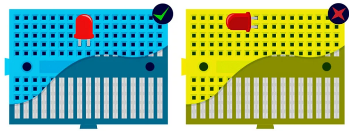
3. TRY THIS: Change the defined constant LED in the previous program from 13 to 12 and connect an external LED to pin 12, and make sure your external LED is flashing the correct message. Important: External LED must be connected in series with resistor! Use breadboard. The following picture explains how breadboard pins are connected inside:

(source https://learn.pimoroni.com/article/anatomy-of-a-mini-breadboard)
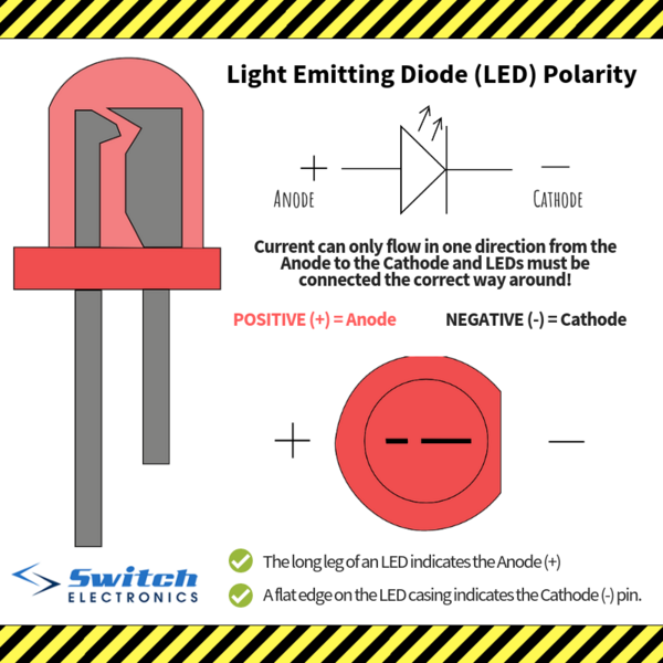
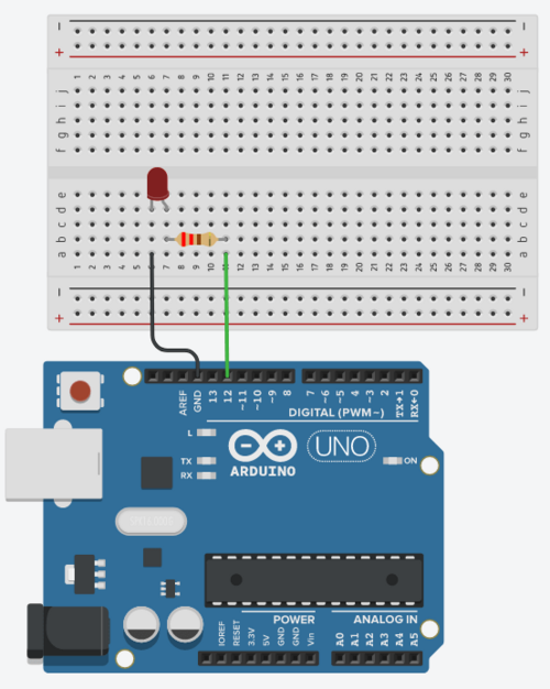
How to connect: Notice that LED has two legs - the longer one (anode) connects to + (i.e. to one leg of resistor), while the shorter one (cathode) connects GND pin of the microcontroller. The other leg of the resistor connects to the digital pin of microcontroller, such as D12.
Look at the following picture to study the conections of LED:

(source https://www.switchelectronics.co.uk/blog/post/ledpolarity.html)
Look at the following picture to study an example how LED connects to microcontroller:

(source https://roboticsbackend.com/arduino-led-complete-tutorial/)
YOUR TASK: connect 3 LEDs (red, yello, green) independently (each one needs its own resistor in series) to three different pins, and create a program that works like traffic lights: first shows red, then red and yellow together, then only green, then only yellow, and finally red again to start over from the beginning.
4. TRY THIS: Test read from touch sensor (the red part that has a little pad with a label TOUCH) and IR sensor (the blue narrow part with two LEDs - black one and transparent one). Both sensors work the same and have the same connections:
- GND - connects to GND on microcontroller
- VCC - connects to 5V on microcontroller
- OUT - digital output - connects to a digital pin of your preference (such as D10) - use that number in the code below
#define IRSENSOR 10
void setup() {
  Serial.begin(9600);
  pinMode(IRSENSOR, INPUT);
}

void loop() {
  int sensor = digitalRead(IRSENSOR);
  Serial.println(sensor);
  delay(300);
}
YOUR TASK: Modify the program in such a way that each time the touch sensor is pressed, the message "click" will be sent to serial console and the internal LED will show light for half a second. If you are fast, try to improve the program to distinguish between a "click" and a "double-click". When double-click is pressed, no click event should be reported.
5. TRY THIS: Insert the black buzzer to breadboard. Connect the pin marked + with some digital pin of microcontroller, and the other one with GND pin. Test the following program. What will happen? Why? How does it work? Note: you will need to send "something" to microcontroller to hear anything.
#define BUZZER 7
#define LED 13
void setup() {
  pinMode(BUZZER, OUTPUT);
  pinMode(LED, OUTPUT);
  Serial.begin(9600);
}

void pipip()
{
  for (int i = 0; i < 400; i++)
  {
    digitalWrite(BUZZER, HIGH);
    delayMicroseconds(800);
    digitalWrite(BUZZER, LOW);
    delayMicroseconds(800);
  }
}

void loop()
{
   if (Serial.available())
   {
      char c = Serial.read();
      if (c == 'p') pipip();
   }
   digitalWrite(LED, HIGH);
   delay(100);
   digitalWrite(LED, LOW);
   delay(300);
}
YOUR TASK: Find the musical tones frequencies table on the internet. Create a program that can play some simple melody consisting of at least 5 tones.
6. TRY THIS: Connect joystick to the microcontroller. The x, y pins connect to analog pins - those marked with A, such as A0, A1, A2, etc. (you can use any of them, but change the program accordingly). You already know how to connect VCC and GND (I hope!). And the SW is the digital switch (when clicking with the joystick) - connect it to some digital pin. Observe the range of outputs from the x, and y.
#define JOY_X 0       // this represents pin A0
#define JOY_Y 1       // this represents pin A1
#define JOY_SW 5      // this represents pin D5

void setup() {
  pinMode(JOY_SW, OUTPUT);
  digitalWrite(JOY_SW, HIGH);   // this turns on internal pull-up, because the switch
                                // has two modes: disconnected or grounded, so we have
                                // to make sure we read logical 1 when it is disconnected
  Serial.begin(9600);
}

void loop()
{
    int x = analogRead(JOY_X);
    int y = analogRead(JOY_Y);
    int sw = digitalRead(JOY_SW);

    Serial.print(x);
    Serial.print(" ");
    Serial.print(y);
    Serial.print(" ");
    Serial.println(sw);
    delay(300);
}
YOUR TASK: Create a program where each movement of the joystick to the left will decrease the value shown by 5 (but no more) and each movement to the right will increase it by 5 (but no more). If you are fast, try to control sound produced by the buzzer using the joystick, or light level of LED (you need to switch it on and off very often, hint: you use analogWrite() function for this - be aware that it works on digital pins! not analog pins, but only those marked with PWM signal).