LQFP32 - programs
Important rules
- connect electronic parts only when the microcontroller is disconnected from the PC
- before connecting the USB cable to PC, double-check the connections of all parts
- if you notice anything strange (some part starts getting unusually warm), immediately disconnect the USB cable from PC
- try to make as little mechanical deformation to the parts so that they can be used after you
- for each task create a new program (CTRL-N) and give them some systematic name, for example XX_name.ino - where XX will be increasing 00, 01, 02, ...
- in your home drive (in net/ folder: from left tab "Places" select your username, then select "net" folder) create a subfolder "arduino/" and store all the programs there. when you try to upload a new program first time to Arduino, and the file is not named&saved yet, Arduino will ask you to save it somewhere, that's your last good opportunity to give it some systematic name
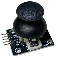
- please place the joystick in the box sideways (laying), not upright (standing).
Getting started in room T3
- start the PC, boot to linux
- open Konsole
- type arduino and press ENTER
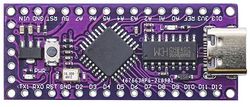
- connect the microcontroller to PC using USB cable
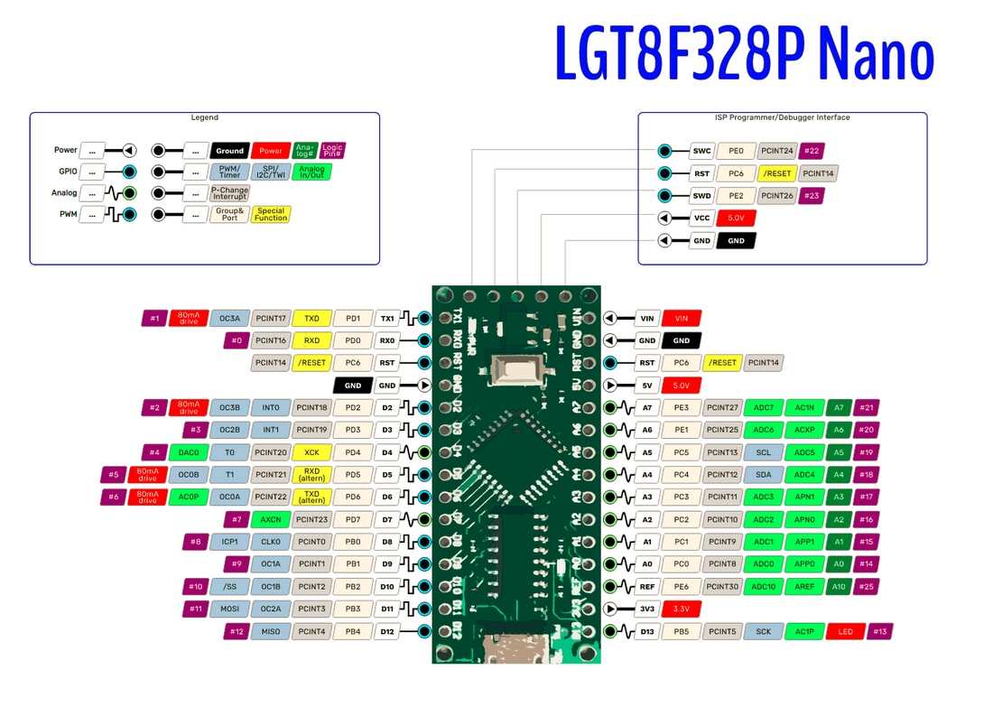
- from menu Tools select Board - LGT8Fx Boards - LGT8F328
- from menu Tools select Port - usually /dev/ttyUSB0
- if you run into problems you may want to check that other settings in Tools are on default values: Clock source: internal 32MHz, clock divider: "1", variant: 328P-LQFP32 (MiniEVB...), SERIAL_RX_BUFFER_SIZE: 64 (normal, upload-speed: 57600
- paste the code in the first task below into program, save the program (CTRL-S) and save it to a new folder your_home_folder/net/arduino and name it 00_output
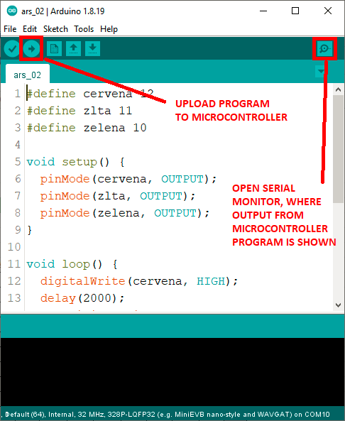
- upload the code (see picture below) and check the serial console, you should see the increasing numbers...
- if you want to use your own PC, ok, all platforms (Linux, Windows, Mac) should work, download arduino (preferably 1.8 (especially if your PC is not very powerful one, but 2.* will also work) and follow this guide: https://github.com/dbuezas/lgt8fx
- useful shortcuts: CTRL-U: upload, CTRL-S: save
TASKS
1. TRY THIS: Test serial port communication. Copy and run the following program. Observe serial monitor. Make sure you select 9600 baud in serial monitor window.
void setup() {
  Serial.begin(9600);
}

int i = 0;
void loop() {
  Serial.print("Hello ");
  Serial.println(i++);
  delay(1000);
}
YOUR TASK: change the program so that after reaching 100, it will start counting in decreasing order, until 0 and then again to 100, etc. Use the operator for decrementing (i--) and if condition:
if (condition)
{
    commands to be executed when condition is satisfied
}
Notice how the variable i of type int is defined in the code above. You may want to define another variable.
What have we learned here?
- use serial output for printing information to serial monitor, which is very useful for debugging our programs.
2. TRY THIS: Test internal LED flashing:
#define LED 13
void setup() {
  pinMode(LED, OUTPUT);
}

void loop() {
  digitalWrite(LED, HIGH);
  delay(500);
  digitalWrite(LED, LOW);
  delay(100);
}
YOUR TASK: change the program so that it will be showing SOS in Morse code.
What have we learned here?
- use digitalWrite(pin, state) function to control digital pins (0 or LOW sets them to 0 Volts, 1 or HIGH sets them to 5 Volts)
- built-in LED is connected to pin 13, it is useful for debugging programs, signaling state, successful connection to devices, etc.
3. TRY THIS: Change the defined constant LED in the previous program from 13 to 12 and connect an external LED to pin 12, and make sure your external LED is flashing the correct message. Important: External LED must be connected in series with resistor! Use breadboard. The following picture explains how breadboard pins are connected inside:
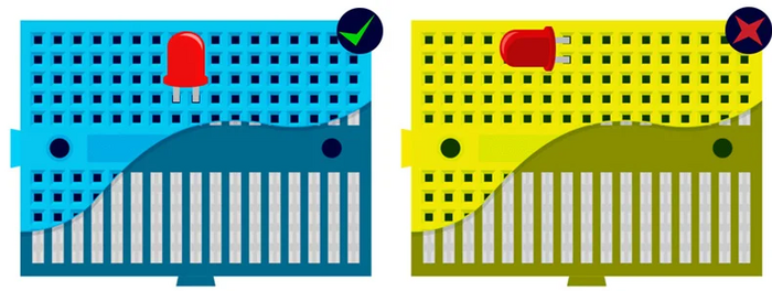
(source https://learn.pimoroni.com/article/anatomy-of-a-mini-breadboard)
How to connect: Notice that LED has two legs - the longer one (anode) connects to + (i.e. to one leg of resistor), while the shorter one (cathode) connects GND pin of the microcontroller. The other leg of the resistor connects to the digital pin of microcontroller, such as D12.
Look at the following picture to study the conections of LED:
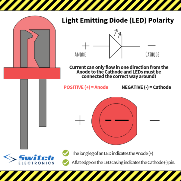
(source https://www.switchelectronics.co.uk/blog/post/ledpolarity.html)
Look at the following picture to study an example how LED connects to microcontroller:
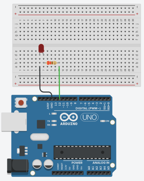
(source https://roboticsbackend.com/arduino-led-complete-tutorial/)
YOUR TASK: connect 3 LEDs (red, yello, green) independently (each one needs its own resistor in series) to three different pins, and create a program that works like traffic lights: first shows red, then red and yellow together, then only green, then only yellow, and finally red again to start over from the beginning.
What have we learned here?
- breadboard is useful for connecting electronic parts in simple circuits
- LED needs a protecting resistor in series, because it has a constant voltage drop and the rest of the voltage has to be consumed by the rest of the circuit
- polarity is important for LED, but it is not important for resistor
- arduino has many digital pins that can control many external devices - even most of the analog pins can be used as digital input/output pins
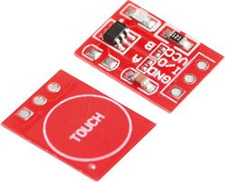
4. TRY THIS: Test reading from touch sensor (the red part that has a little pad with a label TOUCH) and IR sensor (the blue narrow part with two LEDs - black one and transparent one). Both sensors work the same and have the same connections:
- GND - connects to GND on microcontroller
- VCC - connects to 5V on microcontroller
- OUT - digital output - connects to a digital pin of your preference (such as D10) - use that number in the code below
#define TOUCHSENSOR 10
void setup() {
  Serial.begin(9600);
  pinMode(TOUCHSENSOR, INPUT);
}

void loop() {
  int sensor = digitalRead(TOUCHSENSOR);
  Serial.println(sensor);
  delay(300);
}
YOUR TASK: Modify the program in such a way that each time the touch sensor is pressed, the message "click" will be sent to serial console and the internal blue LED will show light for half a second. Even if the press lasts long, only one "click" message should be produced. If you are fast, try to improve the program to distinguish between a "click" and a "double-click". When double-click is pressed, no click event should be reported.
What have we learned here?
- use digitalRead(pin) function to read input from digital pins - when they are connected to 0 Volts (ground), we read 0 bit, when they are connected to 5 Volts, we read bit 1.
- to measure time between events, use the millis() function, which returns the number of milliseconds passed since the program has started
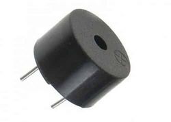
5. TRY THIS: Insert the black buzzer to breadboard. Connect the pin marked + with some digital pin of microcontroller, and the other one with GND pin. Test the following program. What will happen? Why? How does it work? Note: you will need to send "something" to microcontroller to hear anything.
#define BUZZER 7
#define LED 13
void setup() {
  pinMode(BUZZER, OUTPUT);
  pinMode(LED, OUTPUT);
  Serial.begin(9600);
}

void pipip()
{
  for (int i = 0; i < 400; i++)
  {
    digitalWrite(BUZZER, HIGH);
    delayMicroseconds(800);
    digitalWrite(BUZZER, LOW);
    delayMicroseconds(800);
  }
}

void loop()
{
   if (Serial.available())
   {
      char c = Serial.read();
      if (c == 'p') pipip();
   }
   digitalWrite(LED, HIGH);
   delay(100);
   digitalWrite(LED, LOW);
   delay(300);
}
YOUR TASK: Find the musical tones frequencies table on the internet. Create a program that can play some simple melody consisting of at least 5 tones. Please solve it by modifying the function pipip(), do not download a ready song from internet. (you can, bu it does not count).
What have we learned here?
- buzzer is a simple membrane that can produce sound by vibrating, when we alternately send 0s and 1s to a digital pin, where it is connected
- tones have frequencies expressed in Hz, which means how many times some periodic event occurs per second, one instance of such an event lasts certain time, which we call a period. It is easy to calculate period from frequency and vice versa
6. TRY THIS: Connect joystick to the microcontroller. The x, y pins connect to analog pins - those marked with A, such as A0, A1, A2, etc. (you can use any of them, but change the program accordingly). You already know how to connect VCC and GND (I hope!). And the SW is the digital switch (when clicking with the joystick) - connect it to some digital pin. Observe the range of outputs from the x, and y.
#define JOY_X 0       // this represents pin A0
#define JOY_Y 1       // this represents pin A1
#define JOY_SW 5      // this represents pin D5

void setup() {
  pinMode(JOY_SW, INPUT);
  digitalWrite(JOY_SW, HIGH);   // this turns on internal pull-up, because the switch
                                // has two modes: disconnected or grounded, so we have
                                // to make sure we read logical 1 when it is disconnected
  Serial.begin(9600);
}

void loop()
{
    int x = analogRead(JOY_X);
    int y = analogRead(JOY_Y);
    int sw = digitalRead(JOY_SW);

    Serial.print(x);
    Serial.print(" ");
    Serial.print(y);
    Serial.print(" ");
    Serial.println(sw);
    delay(300);
}
YOUR TASK: Create a program where each movement of the joystick to the left will decrease the value shown by 5 (but no more) and each movement to the right will increase it by 5 (but no more). If you are fast, try to control sound produced by the buzzer using the joystick, or light level of LED (you need to switch it on and off very often, hint: you use analogWrite() function for this - be aware that it works on digital pins! not analog pins, but only those marked with PWM signal).
What have we learned here?
- in addition to digital pins, where only logical values 0 and 1 can be written or read, arduino also has analog input pins. They work like voltmeter - and convert the incoming voltage to a value 0-MAX, where MAX depends on the type of arduino. In our case it has 12-bit resolution and thus the values are in the range 0-4095 (standard arduino has 10-bit ADC convertor, and thus a range 0-1023). That is for example 2.5 volts connected will mean we read 2047, 1 volt connected will mean value 819 (=4095/5), etc.
---
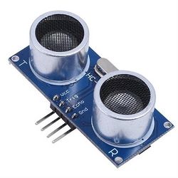
7. TRY THIS: Connect Ultrasonic sensor: GND to GND, VCC to 5V, TRIG to D3, ECHO to D4. Ultrasonic sensor works as follows: TRIG signal is output signal from microcontroller to sensor, and ECHO signal is a response from sensor and inputs to microcontroller. We need to configure the pins accordingly (TRIG as OUTPUT, ECHO as INPUT). The measurement starts by sending a 10 microsecond pulse on TRIG pin. Normally the TRIG pin is LOW (0), but setting it to HIGH (1) for the time interval lasting 10 microseconds starts the measurement. When the measurement is completed, the sensor responds with a pulse on ECHO pin. Normally ECHO pin is LOW (0), and when the sensor sends a response, it turns the ECHO pin HIGH (1) for certain number of microseconds according to this formula: number_of_microseconds = distance[cm] * 58. We therefore need to first send the 10 microsecond pulse on pin TRIG, then wait until ECHO pin becomes HIGH, notice that time (use the function micros() which returns the number of microseconds passed since arduino was reset), then wait until it falls back to LOW, and measure time again. The difference (the length of the HIGH pulse in microseconds) needs to be divided by 58 to get the distance in cm.
The following program calls function measure() that should perform the measurement described here, and prints the measured distance on the terminal. Currently, instead of measurement, it returns a random number.
#define TRIG  3
#define ECHO  4

void setup() {
  pinMode(TRIG, OUTPUT);
  pinMode(ECHO, INPUT);
  Serial.begin(9600);
}

int measure()
{
  return rand() % 100;
}

void loop()
{
    int distance = measure();
    Serial.println(distance);
    delay(300);
}
YOUR TASK: Implement the function measure() so that it will measure the distance to obstacle using ultrasonic sensor.
What have we learned here?
- some sensors are more complex than simple digital or analog inputs and they have a particular communication protocol, which we can usually find in datasheet (each electronic part has a datasheet, where we can find all information, maximum ratings, etc.). For example, this part has a product type name HC-SR04, and its datasheet is easy to find on-line: HC-SR04.
- ultrasound is a sound that human ear cannot detect, because it has too high pitch = too high frequency, typically around 20 KHz.
- ultrasonic waves are useful for measuring distances and detecting obstacles.
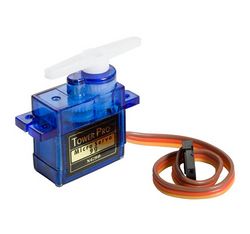
8. TRY THIS: Connect servo to microcotroller: The dark cable (brown) to GND, the red to 5V and the yellow to D5. Servo motor is such a motor which position can be controlled by microcontroller. Its purpose is not to rotate all the way around and propel a vehicle. It can only turn to a specified position 0 - 180 degrees. The position is requested by the microcontroller through the yellow pin: microcontroller sends a pulse (similar to triggering ultrasonic measurement in previous task) which is 500 - 2500 microseconds long. This pulse needs to be sent every 20 milliseconds again and again. In order to move the servo to one extreme (0 degrees), send 500 microseconds pulse, in order to set it to other extreme (180 degrees), set it to 2500 microseconds, and use any value in between accordingly. The following program allows the user to control servo using + and - characters sent over serial console. Instead of controlling the servo, it only prints a message.
#define SERVO_PIN 5

int position;

void setup() {
  pinMode(SERVO_PIN, OUTPUT);
  Serial.begin(9600);
  position = 90;
}

void set_servo(long angle)
{
  // tu poslite pulz podla hodnoty angle
}

void show_servo(int angle)
{
  Serial.print("setting servo to ");
  Serial.print(angle);
  Serial.println(" degrees.");
}

void loop()
{
    if (Serial.available())
    {
       char c = Serial.read();
       if (c == '+')
       {
          if (position < 180) position++;
       }
       else if (c == '-')
       {
          if (position > 0) position--;
       }
       show_servo(position);
    }
    set_servo(position);
    delay(20);
}
YOUR TASK: Modify the program by implementing the function set_servo() so that it sends out a correct pulse to servo motor. By pressing '+' and '-' keys you will be able to turn servo to any position. Recommendation: use Putty instead of Arduino Serial console as it sends the pressed key immediately to serial console.
What have we learned here?
- servo-motors are special motors that allow controlling their position. They contain a DC motor, a potentiometer for detecting the current position, and built-in electronics that controls them. That's why they are very convenient for use with microcontrollers, because the control signal (yellow, white or orange cable) can be connected directly to a digital ouput pin of microcontroller without the need for external driver circuit.
- servos are controlled by width of a positive pulse on a digital line. This kind of control is usually called PWM = pulse-width modulation.
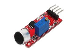
9. TRY THIS: Connect microphone to micontroller: GND to GND, + to 5V, and the remaining pin to A1. Microphone sensor measures the sound wave, and always returns the current displacement of the wave in its range. Therefore, when it is quite, it will return about the same value (maybe 200, 300, or anything else - depending how it tuned - use screwdriver to tune it). As soon as there is sound in the environment the signal will start oscillating around that "quite value" - for instance from 150 to 250, when the quite value was 200, and the amplitude is 50. When sound will be stronger, louder, the amplitude will be higher. The following program measures the current amplitude of microphone.
#define MICROPHONE 1

int position;

void setup() {
  Serial.begin(9600);
}

int measure_amplitude()
{
  int min = 1023;
  int max = 0;
  for (int i = 0; i < 5000; i++)
  {
    int val = analogRead(MICROPHONE);
    if (val > max) max = val;
    if (val < min) min = val;
  }
  return (max - min) / 2;
}

void loop()
{
    int loudness = measure_amplitude();
    Serial.println(loudness);
    delay(100);
}
YOUR TASK: Connect the buzzer (speaker) to some digital pin (do not forget to configure it as output), and make a program which will start alarm after three strong sound impulses (such as clapping hands).
What have we learned here?
- this kind of microphone outputs an analog signal wave that directly represents the audio wave it is detecting from the environment. Arduino has enough computational power to analyze this sound - determine frequence, amplitude or type of the sound wave
- blowing into a microphone generates strong excitation of its sensor and can replace laud clapping. :)
10. YOUR TASK: Connect joystick and servo to microcontroller. Write a program which will read the position of the joystick (left - right) and set the servo to the corresponding position. Moving the joystick up or down, or clicking it (you can choose one or all of these options) will fix the servo in that position until it is clicked (moved up or down) again so that its position will again be changed.
What have we learned here?
- Arduino is a wonderful microcontroller, which can be connected with many devices at the same time and as a result be a controller of more complex electronic devices, with various sensors and actuators. A typical example appliction is a robot.
11. TRY THIS: The following program will allow the user to enter several values. It will remember the values in a one-dimensional array. When the user enters 0, he or she indicates the end of the input sequence. After that, the program prints all the numbers from the sequence.
#define MAX_COUNT 10

int numbers[MAX_COUNT + 1];
int count;

void setup() {
  Serial.begin(9600);
  Serial.setTimeout(10000);
  count = 0;
  Serial.println("Enter numbers, terminate the sequence with 0");
}

void show_numbers()
{
    for (int i = 0; i < count; i++)
      Serial.println(numbers[i]);
    count = 0;
    Serial.println("You can enter new sequence.");
}

void loop()
{
    if (Serial.available())
    {
      int n = Serial.parseInt();
      numbers[count] = n;
      count++;
      if (count == MAX_COUNT)
      {
         Serial.println("maximum sequence length reached, terminating sequence.");
         numbers[count++] = 0;
      }
      if (numbers[count - 1] == 0)
        show_numbers();
    }
}
YOUR TASK: Using the idea shown above, write a program which will wait for several hand claps of the user. After a period of silence, it will repeat the same rythm. Use the function millis() to measure time elapsed between individual claps and store these time intervals in the array as shown above.
What have we learned here?
- One-dimensional arrays are useful data structures. Among other uses, they can store a sequences of events that can be analyzed, replayed or recognized. A nice extension of this task would be to record several sequences and then detect which of those recorded sequences was repeated in the next recording trial.
- Arduino has very little memory - for standard Arduino it is only 2 KB of RAM, so we have to use it in a very efficient way, and use low-level language like C to avoid overheads in memory usage. Another reason to use C language is that we have a very good control over run-time and can read and write signals with very high precision in timing.
12. YOUR TASK: A CREATIVE PROJECT. Think about an interesting (and funny!) project that will use at least three different devices connected to the microcontroller. Use your creativity.
What have we learned here?
- Now you know the basics of programming microcontrollers. Look around and see how many low-cost sensors are on the market and even near to you.
- Get creative, think about something useful, or entertaining that you could build and program. Design and model for it (for instance in TinkerCAD, and visit FabLAB to get help with printing it on a 3D printer, or produce it with laser cutter. You can register for a course Digital Technologies of Fabrication. Good luck!
