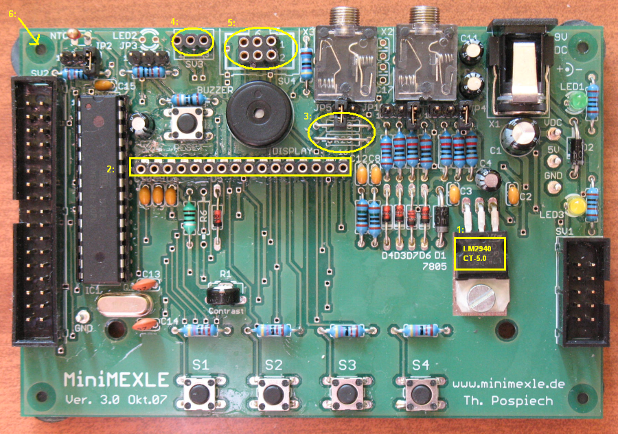
MiniMexle board building
Building
Although on the Mexle website You can find the complete step-by-step manual of the board population, we present here our ideas. Instead of building the whole board on the one step, we start with the blocks, which can work independently.
First we start to build power supply (i.e. C1-C4, R2, D1, D2, LED, connector X1, test pins and power supply stabilizer 7805). If You plan to use this board on battery powered applications, You can immediately replace 7805 stabilisator with low-drop version e.g. National Semiconductor LM2940CT-5.0.
After completing test the power supply immediately. See the Fig. 20 and 21 in the manual to find all the points where the voltage should be measured.
Error: The +5V is on the wrong pin in the Fig. 20 manual v3.0.
Next step is to populate board with the all necessary power filter capacitors, reset circuit and
an oscillator circuit together with a processor socket. Also the connectors SV1 (ISP Programmer)
and SV2 (processor pins) are on the place.
Without processor on the place test the function of the Reset circuit.
Then You can insert the processor and using the AVR-USB-PROGI You can check if the programmer
is able to read configuration fuses and device signature.
If Yes, then the board is good and You can finish the board population.
Error: The jumper labeled SJ3 on the board is labeled SJ2 in the schematic diagram on p. 7 in manual v3.0.
Last step is to download the test program and check if everything is OK.
ToDo: The source code of the test program is missing
ToDo: The fuse setting picture here
Changes
Following changes were realized on my board to improve it:
1. Low-drop version of the stabilisator is used
See http://www.national.com/mpf/LM/LM2940.html
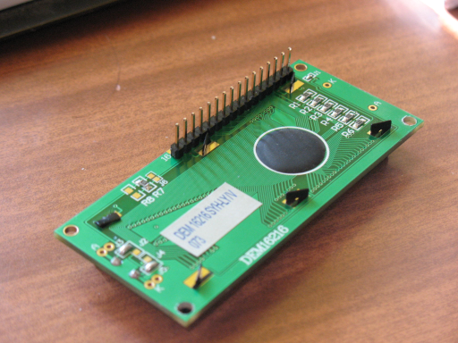
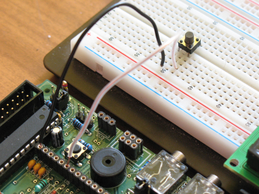
2. Display is equipped with pins, board with holes. This enables to use the display also with a solderless breadboard. Also the holes in the MiniMexle board makes easier to connect wires to the breadboard.
3. For the same reason I used three holes on the place of the SV3 connector.
4. I did not use the RC filter on the PWM outputs, i.e. don't solder the capacitors C16 and C17 and use wire instead R20 and R23. It is important if You plan to use PWM outputs for motor control.
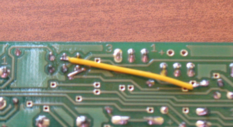
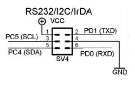
5. For easier interfacing with a serial communication link I did change slightly the SV4 connector
6. And finally, I used the rubber stamps on the bottom to save my table
I did also change the connection of the SV4 connector in order to have the serial link
on the three successive pins, which makes easier external connections.
