New life for MiniMexle
In following text you'll find an information about MiniMexle board hacking to make it Arduino compatible. It is easy and brings new life to your board.
Step by step
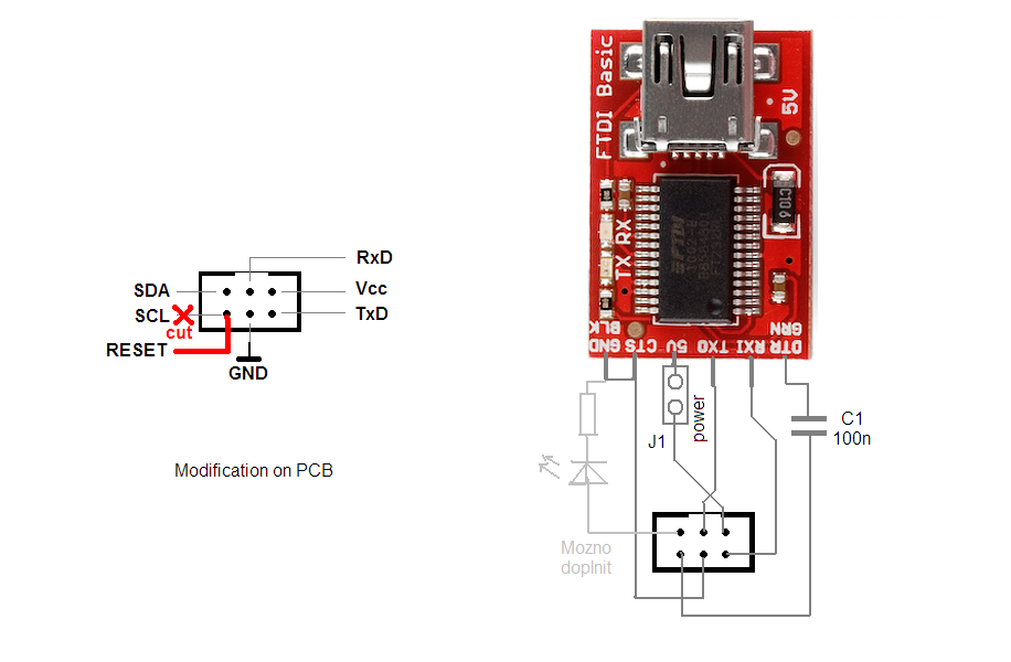
First, we need to access RxD, TxD, Vcc, GND and Reset signals and prepare them for USB converter to be able upload compiled programs using an Arduino bootloader. Unfortunately, those signals are not available at the same place. It is necessary to modify the SV4 connector. It originally contains signals RxD and TxD, Vcc, GND and SCL + SDA (i2c bus). All we need to change is to replace one of the i2c bus signals with RESET. This can be done by cutting the trace at the bottom of the board from PIN 6 of the SV4 connector and connecting it to the nearby via:
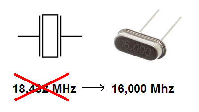
Second important change is replacement of the original 18,432 MHz crystal with the 16,000 MHz one. It would be possible to modify the Arduino bootloader to work also with the original frequency, but it would also require modifying all the Arduino libraries, so the replacement seems to be easier. After this you have a 100% compatible Arduino clone based on the ATmega328P processor.
Example 1
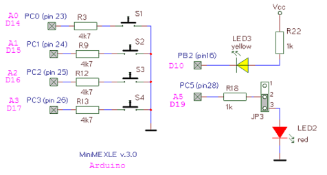
MiniMEXLE board contains 2 LEDs (red and yellow) and 4 pushbuttons (labeled SW1-SW4). See schematic:
Pushbuttons S1 to S4 are connected to the pins PC0 - PC3 (i.e. D14-D17 in Arduino lingo) and are active LOW. Yellow LED is connected to the PB2 (Arduino D10) and also is active LOW. Second, red LED is active HIGH an connected to the pin PC5 (Arduino D19). All the switches and red LED are shared with an analog inputs A0-A5.
Following program shows their use in a simple Arduino code:
/*
  MiniMEXLE Test program 1
  Tests both LEDs and pushbuttons

  (c) XII. 2013 Richard Balogh
 */


#define SW1 A0
#define SW2 A1
#define SW3 A2
#define SW4 A3

#define RedLED A5
#define YellowLED 10

void setup() {

  pinMode(RedLED, OUTPUT);
  pinMode(YellowLED, OUTPUT);

// Switches:
  pinMode(SW1, INPUT);
  digitalWrite(SW1, HIGH);  // set pullup on analog pin 0
  pinMode(SW2, INPUT);
  digitalWrite(SW2, HIGH);  // set pullup on analog pin 0
  pinMode(SW3, INPUT);
  digitalWrite(SW3, HIGH);  // set pullup on analog pin 0
  pinMode(SW4, INPUT);
  digitalWrite(SW4, HIGH);  // set pullup on analog pin 0
}

void loop() {

  if( digitalRead(SW1) == LOW )      // Buttons are active low!
      digitalWrite(RedLED, HIGH);    // turn the LED on (HIGH is the voltage level)
  else
      digitalWrite(RedLED, LOW);     // turn the LED on (HIGH is the voltage level)

  if( digitalRead(SW2) == LOW )      // Buttons are active low!
      digitalWrite(YellowLED, HIGH);    // turn the LED on (HIGH is the voltage level)
  else
      digitalWrite(YellowLED, LOW);     // turn the LED on (HIGH is the voltage level)

  if( digitalRead(SW3) == LOW )      // Buttons are active low!
   {
      digitalWrite(RedLED, HIGH);   // turn the LED on (HIGH is the voltage level)
      delay(200);               // wait for a second
      digitalWrite(RedLED, LOW);    // turn the LED off by making the voltage LOW
      delay(200);               // wait for a second
   }


  if( digitalRead(SW4) == LOW )      // Buttons are active low!
   {
      digitalWrite(YellowLED, HIGH);   // turn the LED on (HIGH is the voltage level)
      delay(200);               // wait for a second
      digitalWrite(YellowLED, LOW);    // turn the LED off by making the voltage LOW
      delay(200);               // wait for a second
   }

}
Pin mapping
The analog pins can be used identically to the digital pins, using the aliases A0 (for analog input 0), A1, etc. For example, the code would look like this to set analog pin 0 to an output, and to set it HIGH:
pinMode(A0, OUTPUT);
digitalWrite(A0, HIGH);


