Difference between revisions of "Spike Prime - Rotational Inertia"
(Created page with "== Let's begin == introduction... == Build == Model: model of vehicle|300px Pictures: Image:spike_average_speed.jpg|vehicle|300...") |
m |
||
| (5 intermediate revisions by the same user not shown) | |||
| Line 1: | Line 1: | ||
| + | <small>(''[[Spike up Prime Interest in Physics|back to list of projects]]'')</small> | ||
| + | |||
== Let's begin == | == Let's begin == | ||
| − | + | When you lift and spin a wheel of a bicycle, it will continue rotating for quite a while, large portion of its mass is distributed on its circumference. Would it be rotating for the same duration if its mass would be placed more close to the center of rotation? In this exercise, we will try to find out. | |
== Build == | == Build == | ||
| Line 7: | Line 9: | ||
Model: | Model: | ||
| − | [[Image: | + | [[Image:spike_moment_of_inertia_model.png|model of vehicle|300px]] |
Pictures: | Pictures: | ||
| − | [[Image: | + | [[Image:spike_moment_of_inertia_robot.jpg|picture of the system|300px]] |
| + | [[Image:spike_moment_of_inertia_detail.jpg|detail of mechanism|300px]] | ||
Building instructions: | Building instructions: | ||
| − | * [[Spike Prime - | + | * [[Spike Prime - Moment of Inertia - Building Instructions|Moment of Inertia (PNG)]] |
Download building instructions: | Download building instructions: | ||
| − | * [[Media: | + | * [[Media:spike_moment_of_inertia.pdf| whole system (pdf)]] |
Download stud.io model: | Download stud.io model: | ||
| − | * [[Media: | + | * [[Media:spike_model_of_inertia.io|vehicle (stud.io)]] |
| + | |||
| + | The model has two motors: the upper motor has the purpose to set the freely rotating part into rotation. The role of the bottom motor is to automatically connect and disconnect the gears so that the rotating part will only continue the rotation due to its inertia after it has been speeded up. The yellow bricks at the top are reflecting light of the color sensor very well and thus the system can determine, whether the rotation has seized or still takes place. The wheels, representing the weight, can be inserted at several different positions at the arms. However, remember to always place them in symmetric positions so that the whole rotating part is balanced and doesn't waggle. | ||
| + | |||
| + | Connections: | ||
| + | |||
| + | * upper motor - F | ||
| + | * lower motor - E | ||
| + | * color sensor - D | ||
== Program == | == Program == | ||
| − | [[Image: | + | [[Image:spike_model_of_inertia_prg1.png|Accelerate]] |
| + | [[Image:spike_model_of_inertia_prg2.png|Measurement]] | ||
| − | Download: [[Media: | + | Download: [[Media:moment_of_inertia.llsp|moment_of_inertia.llsp]] |
| − | |||
| − | |||
| + | The program is using the variable speed to accelerate slowly to avoid gear teeth to beat each other. | ||
| + | When starting the program, the two motors are aligned. | ||
| + | After the full speed is reached, the upper motor is disconnected by turning the bottom motor slightly. | ||
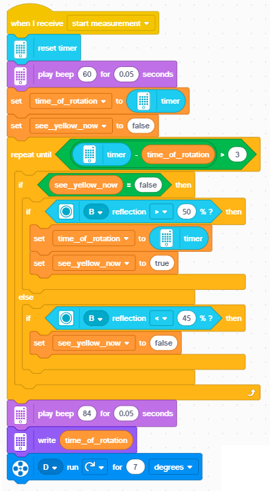
| + | The sensor then starts to permanently look for changes of reflection detected by the sensor. As soon as there comes no change in three consecutive seconds, the rotation is considered to have seized, and the timer value of the last time the reflection onset was detected is reported in the time_of_rotation variable, and it is shown on the display. | ||
== Measure, analyze, think == | == Measure, analyze, think == | ||
| − | <youtube> | + | <youtube>XmbaqS5YdZs</youtube> |
* Make your own recording | * Make your own recording | ||
| Line 44: | Line 58: | ||
Example result of measurement: | Example result of measurement: | ||
| − | [[Image: | + | [[Image:spike_moment_of_inertia_variables.png|result of measurement]] |
* Perform measurements with your model and discuss in your group what has happened. | * Perform measurements with your model and discuss in your group what has happened. | ||
| Line 51: | Line 65: | ||
== Explore and modify == | == Explore and modify == | ||
| − | * | + | * You can try to use other weight elements in addition to the wheels and compare the results. |
| − | * | + | * You can try to make the arms even longer. |
| + | * will the outcome change, if the same weight is distributed along four arms instead of two? | ||
| + | * Replace the two gray gear wheels with two gear wheels of different sizes to make the spinning part rotate faster or slower. Perform the same measurements and note the difference. How does this difference relate to the new gear ratio? Can you try to analyze and investigate this relation? | ||
| + | * Find your own idea for modification of the model or the experiment! | ||
| + | |||
== Present == | == Present == | ||
| Line 61: | Line 79: | ||
== Additional resources == | == Additional resources == | ||
| − | * Download: [http://robotika.sk/spike/ | + | * Download: [http://robotika.sk/spike/spike_physics_3_rotational_inertia.zip Moment of inertia - all media files] |
__notoc__ | __notoc__ | ||
Latest revision as of 09:55, 1 October 2020
Let's begin
When you lift and spin a wheel of a bicycle, it will continue rotating for quite a while, large portion of its mass is distributed on its circumference. Would it be rotating for the same duration if its mass would be placed more close to the center of rotation? In this exercise, we will try to find out.
Build
Model:
Pictures:
Building instructions:
Download building instructions:
Download stud.io model:
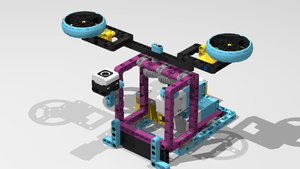
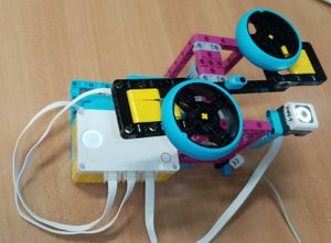
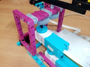
The model has two motors: the upper motor has the purpose to set the freely rotating part into rotation. The role of the bottom motor is to automatically connect and disconnect the gears so that the rotating part will only continue the rotation due to its inertia after it has been speeded up. The yellow bricks at the top are reflecting light of the color sensor very well and thus the system can determine, whether the rotation has seized or still takes place. The wheels, representing the weight, can be inserted at several different positions at the arms. However, remember to always place them in symmetric positions so that the whole rotating part is balanced and doesn't waggle.
Connections:
- upper motor - F
- lower motor - E
- color sensor - D
Program
Download: moment_of_inertia.llsp
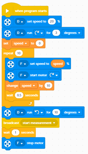
The program is using the variable speed to accelerate slowly to avoid gear teeth to beat each other. When starting the program, the two motors are aligned. After the full speed is reached, the upper motor is disconnected by turning the bottom motor slightly. The sensor then starts to permanently look for changes of reflection detected by the sensor. As soon as there comes no change in three consecutive seconds, the rotation is considered to have seized, and the timer value of the last time the reflection onset was detected is reported in the time_of_rotation variable, and it is shown on the display.
Measure, analyze, think
- Make your own recording
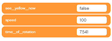
Example result of measurement:
- Perform measurements with your model and discuss in your group what has happened.
Explore and modify
- You can try to use other weight elements in addition to the wheels and compare the results.
- You can try to make the arms even longer.
- will the outcome change, if the same weight is distributed along four arms instead of two?
- Replace the two gray gear wheels with two gear wheels of different sizes to make the spinning part rotate faster or slower. Perform the same measurements and note the difference. How does this difference relate to the new gear ratio? Can you try to analyze and investigate this relation?
- Find your own idea for modification of the model or the experiment!
Present
- Prepare a short presentation for other groups. Tell others about how your measurement went, what issues did you have to solve. What do they mean and why did they happen?
Additional resources
- Download: Moment of inertia - all media files
